Table of Contents
A practical view on protecting power modules, DC bus, and output circuits
In EV charging systems, fuse selection is often treated as a secondary task.
Power modules, cooling, communication, and certification usually get the most attention.
Fuses are added later—often selected based on voltage and current alone.
That approach works in simple systems.
But in DC fast charging, it’s usually not enough.
Because inside a charging station, electrical behavior changes depending on where you look—and faults don’t behave the way most people expect.
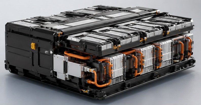
Start with the structure of the charging system
Before talking about fuse types, it helps to look at how a DC charging station is actually built.
Most systems include three key areas:
- Power module (AC/DC conversion stage)
- DC bus (internal distribution)
- Output stage (toward the vehicle)
Each of these has a different role—and different protection requirements.
If you treat them the same, fuse selection becomes guesswork.
The power module: fast faults, expensive damage
The power module is where AC is converted to DC and regulated.
Inside, you typically have:
- IGBT or SiC modules
- Rectification and switching stages
- High-frequency operation
When a fault happens here, it happens fast—and the damage can be immediate.
This is why protection at this level is focused on:
👉 speed and energy limitation
The fuse is not there to protect cables or general circuits.
It is there to protect semiconductor devices.
That usually means:
- Fast interruption
- Low let-through energy (I²t)
- High breaking capacity
If the fuse reacts too slowly, the damage is already done.
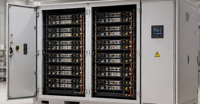
The DC bus: not fast, but not simple either
The DC bus connects multiple power modules and distributes energy inside the system.
Compared to the power module, faults here are:
- Less dynamic
- More influenced by system layout
- Often fed by multiple sources
This is where many designs become inconsistent.
Some systems use high-speed fuses everywhere.
Others rely only on upstream protection.
Neither approach is ideal.
At the DC bus level, protection needs to balance:
- Fault interruption capability
- Stability under normal load
- Coordination with upstream and downstream devices
It’s less about speed, and more about control.
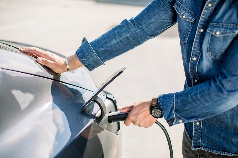
The output side: where system meets the vehicle
At the output stage, the charging station connects directly to the EV.
This introduces a different set of concerns:
- External faults (cable damage, connector issues)
- User interaction
- Variable load conditions
Faults here are not always high-energy events.
They can be:
- Intermittent
- Medium-level overcurrent
- Influenced by the vehicle side
This means protection must be:
- Reliable
- Stable
- Coordinated with system controls
Overly fast protection can cause unnecessary trips.
Slow protection can expose the system to risk.
Not all DC faults behave the same
One common assumption is:
👉 “A fault means maximum short circuit”
In charging systems, that’s not always true.
You may see:
- Controlled shutdown faults
- Partial faults inside modules
- Cable or connector issues
Some faults develop gradually.
Some are limited by system electronics.
That’s why fuse selection cannot rely on a single condition.
You need to consider:
- Fault type
- Fault path
- System response
Why fuse selection is different from PV or ESS
Charging systems sit somewhere between PV and ESS.
They are not purely generation systems (like PV).
They are not purely storage systems (like ESS).
They are power conversion systems with dynamic loads.
That changes the protection logic.
- PV → focus on reverse current and low fault current
- ESS → focus on battery behavior and sustained faults
- Charging → focus on power electronics and system coordination
Trying to apply PV or ESS fuse logic directly to charging systems often leads to mismatches.
Fuse and system coordination
In charging stations, fuses are only one part of the protection system.
They must work together with:
- Contactors
- Control systems
- Protection logic inside power modules
If coordination is not considered:
- Fuses may trip during normal operation
- Or fail to clear faults in time
- Or conflict with system shutdown logic
The goal is not just protection—it’s predictable behavior under fault conditions
What engineers should define first
Before selecting a fuse, it helps to define a few basic things:
- Where the fuse is installed (module / DC bus / output)
- What equipment it is protecting
- Expected fault behavior
- System voltage and current
- Interaction with control systems
Once these are clear, selection becomes much more straightforward.
Final thought
Charging station fuse selection is not complicated—but it is easy to oversimplify.
Most issues don’t come from the fuse itself.
They come from misunderstanding how the system behaves under different conditions.
If you treat all parts of the system the same, protection will be inconsistent.
If you match protection to function, the system becomes much more stable.
Need a second opinion?
If you’re working on a DC charging system and want to review your fuse selection:
Share your system details—application area, voltage, current, and protection target.
We can help you identify practical fuse options based on real operating conditions.