How to Select the Right Fuse for Battery Racks, DC Bus, and PCS
When engineers design protection for energy storage systems (ESS), one common mistake is treating fuses like standard industrial DC components.
In reality, ESS applications are fundamentally different.
Battery systems operate under high DC voltage, dynamic charge and discharge cycles, and complex fault conditions that do not behave like traditional AC systems. This means fuse selection must be based on real system behavior—not just ratings on a datasheet.
Where Fuses Are Used in ESS
Before selecting a fuse, the most important question is:
Where is the fuse installed?
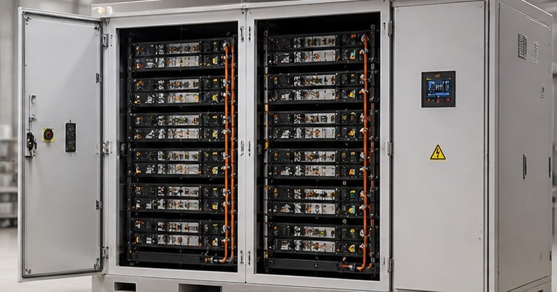
In a typical ESS, fuses are used in four main locations:
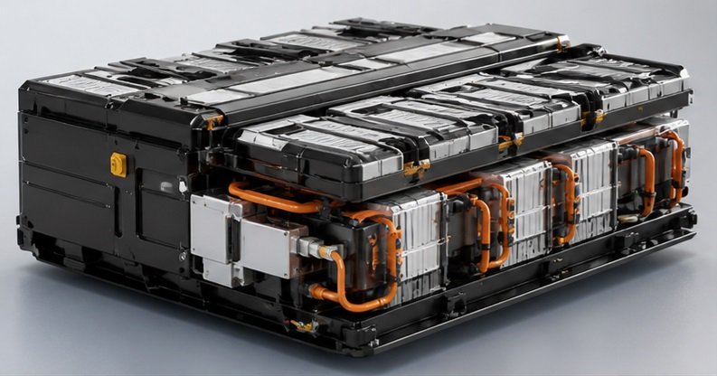
- Battery module or pack
- Battery rack
- DC combiner or DC panel
- PCS (converter / inverter) input
Each position requires a different protection approach.
At the module level, the goal is to prevent internal faults from spreading.
At the rack level, fuses isolate larger faulted sections.
In DC panels, they protect aggregated circuits and switching equipment.
At the PCS side, fuses are used to protect sensitive semiconductor devices.
Using the same fuse type across all these locations often leads to poor protection performance.
Why Current Rating Alone Is Not Enough
A common shortcut in fuse selection is matching the current rating to the system load.
For ESS, this approach is incomplete.
Proper fuse selection depends on multiple factors:
- System voltage
- Continuous operating current
- Available fault current
- Time constant of the system
- Ambient conditions such as temperature and airflow
- Load profile (steady vs cyclic operation)
Battery systems rarely operate under constant conditions. Charge and discharge cycles introduce thermal and electrical variations that directly affect fuse performance.
Selecting a fuse based only on nominal current can result in nuisance tripping or insufficient protection.
Always Design Around System Voltage
Another critical point is voltage selection.
In ESS design, fuses must be rated according to the system voltage, not the voltage of individual battery modules.
For example:
A battery rack operating at 1500V DC requires fuses that are fully rated for 1500V DC—even if individual modules operate at much lower voltage.
Incorrect voltage selection can lead to unsafe interruption behavior during faults.
Understanding Battery Fault Behavior
Not all faults in battery systems are high-energy short circuits.
In practice, two main types of faults exist:
- Low-resistance faults → fast, high-energy discharge
- High-resistance faults → slower, less obvious, but still dangerous
High-resistance faults may appear as gradual voltage drops or abnormal self-discharge, making them harder to detect but still critical.
Because of this, battery protection often requires full-range fuse behavior, capable of responding to both overload and short-circuit conditions.
This is different from PCS protection, where fast semiconductor protection is usually the priority.
Fuse and Contactor Coordination
In most ESS designs, fuses do not operate alone.
They are typically used together with contactors:
- Contactors handle normal switching and low-level faults
- Fuses clear high fault currents
Proper coordination between these components is essential.
A well-designed system ensures that:
- Faults are cleared quickly
- Equipment is protected from damage
- Unnecessary fuse operation is avoided
This usually requires checking breaking capacity, fault current levels, and time-current characteristics.
Different Protection Goals: Battery vs PCS
One of the most important distinctions in ESS fuse selection is the difference between battery-side protection and PCS-side protection.
Battery side
Battery circuits require protection against both overload and short-circuit conditions.
This typically involves full-range fuse characteristics.
Relevant standards include:
- IEC 60269-7
- UL 248-21
PCS / inverter side
PCS circuits focus on protecting semiconductor devices, which are highly sensitive to overcurrent.
This requires fast-acting, high-speed fuse protection.
Relevant standards include:
- IEC 60269-4
- UL 248-13
Using the wrong fuse type in either location can result in incomplete protection or equipment damage.
Installation Considerations
Even a correctly selected fuse can fail if it is not properly installed.
Key factors include:
- Proper fuse holder or mounting system
- Thermal connection to busbars or cables
- Ambient temperature and ventilation
- Correct replacement practices
For NH-type fuses, special attention is required. Incorrect replacement with a higher-rated fuse can compromise system protection.
Proper installation ensures that the fuse performs as expected under real operating conditions.
How to Start ESS Fuse Selection
Instead of asking “Which fuse should I use?”, a more effective approach is to define your system first.
Key parameters include:
- System voltage
- Continuous current
- Installation point
- Available fault current
- Protection target (module, rack, DC bus, or PCS)
With these inputs, engineers can identify suitable fuse options and ensure proper system coordination.
Final Thought
In energy storage systems, fuse selection is not about choosing a product from a catalog.
It is about understanding how the system behaves under fault conditions—and designing protection accordingly.
Need Help Selecting the Right Fuse?
If you are working on an ESS project and need support with fuse selection:
Share your system parameters, including voltage, current, and installation point.
We can help you identify 3–5 suitable fuse options based on real application conditions.